






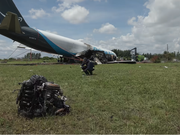














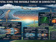























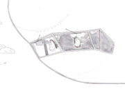

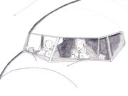



High ice water content (HIWC), which results in ice crystal icing (ICI) is perhaps one of the most counterintuitive traps in modern commercial aviation. Consider cruising at flight level 370, smoothly gliding through the upper edges of a vast, decaying anvil miles away from the primary updraft core of a thunderstorm. The ride is smooth or accompanied by minor light chop. There is no ambient liquid water, no ice building up on the windshield wipers or wings’ leading edges, and the airborne weather radar directly ahead looks completely clean. Then, without warning, the engine instruments tell a different story: a sudden N1 or N2 rollback, engine vibrations, EGT or TGT fluctuations, an uncommanded engine power loss, or a compressor stall. Other anomalies may include Total Air Temperature (TAT) probe providing corrupt or intermittent failure as ice crystals accrete inside or block the probe, small water droplets may appear on heated flight deck windscreens because ice crystals melt upon impact with the warm glass, and the awe-inspiring St. Elmo's Fire. Welcome to Ice Crystal Icing (ICI) i.e., a high-altitude atmospheric phenomenon that bypasses traditional airframe ice detection that continues to challenge high-bypass turbofan engines across the globe.
Case Study: High-Altitude Engine Rollback via Ice Crystal Icing Etihad Airways Flight EY 460 from Abu Dhabi, U.A.E. to Melbourne, Australia
The February 2013 incident involving an Etihad Airways A340-600 provides a compelling case study on how ice-crystal ingestion can simultaneously disrupt air data sensors and induce severe engine mechanical anomalies despite weather radar showing no heavy precipitation and standard airframe ice detection systems remaining silent. After encountering high-altitude convective icing, the aircraft experienced intermittent pitot probe blockages, resulting in an automated flight control reversion to alternate law and loss of autopilot. Compounding the system degradation, the No. 2 engine registered high N1 vibrations (peaking at 7.1 units) caused by water and ice crystal ingress, which subsequently froze and created an ice out-of-balance condition within the spinner assembly. Although engine anti-ice systems were active, they proved ineffective at clearing the spinner accretion until the aircraft descended into warmer air at FL290, where the ice fragmented and melted. This event highlights how high-altitude ice crystal environments pose dual operational threats that simultaneously compromise flight instruments and mechanical powerplant integrity.
For decades, conventional wisdom held that high-altitude ice particles pose little risk to aircraft because they lack liquid water. The logic seemed sound! Solid ice particles simply bounce off cold airframe surfaces. However, deep convective storms, especially in tropical and oceanic convective regions, act as massive moisture elevators. Strong core updrafts lift vast amounts of water vapor into freezing temperatures high above the freezing level. As these updrafts glaciate, they spew out microscopic, high-concentration ice crystals into the surrounding anvil clouds. The thermodynamic sequence for icing inside a turbofan engine unfolds through three distinct phases:





- Ingestion: Microscopic ice crystals (often individual particles measuring only 40 to 200 microns) pass through the fan section unhindered.
- Convective Melting: As these crystals move deeper into the engine core toward the High-Pressure Compressor (HPC), compression heating warms the surrounding air above 0ºC . The ice particles partially melt, creating a thin, wet liquid film over internal components like stator vanes and core ducting.
- Internal Accretion and Shedding: Subsequent incoming dry ice crystals stick to this wet film, rapidly cooling the metal surfaces back down to the freezing point. Ice builds up deep inside the engine core. Eventually, this internal ice block distorts airflow, causing compressor stalls, rollbacks, or sheds entirely and thus extinguishing the flame in the combustor.
The Boeing database captured 174 reported jet engine icing events worldwide as of January 2019 (Bravin and Strapp, 2020).

The Cockpit Radar Trap: Why Modern Radar Is “Blind” to ICI
Airborne weather radar relies on Rayleigh scattering. The energy reflected to the antenna is proportional to the diameter of the target to the sixth power D6 i.e., Reflectivity ∝ D6. Liquid water drops are large and highly reflective, returning bright red and amber cells. In contrast, high-altitude ice crystals in an anvil are tiny, low-mass, and possess a low dielectric constant. Because radar return is dominated by particle size, a high-density “soup” of billions of small ice crystals 40−200 μm yield low reflectivity , creating a “radar-blind” environment despite high mass concentrations (>1−3gm⁻³).
Your radar display might show a completely clear path, or at most a faint green haze, masking a high risk for engine icing. Avoiding ICI requires active, manual radar management rather than relying solely on auto-tilt modes tuned strictly for lower-level liquid hazards.
If operating in IMC above or near convective activity, manually tilt your radar down to scan the lower levels (typically F150 FL200) near or below the freezing level. This radar scanning technique below the freezing level detects falling ice crystals melting into liquid water drops. If you see strong red, amber or yellow returns directly below your flight path, the upper levels of that column even if clear on radar are likely saturated with invisible high-density ice crystals.

Passive Remote Sensing
Satellite imagery also plays a critical role in identifying regions ripe for ice crystal icing by leveraging distinct spectral channels to locate deep convective clouds and high-altitude outflow anvils. Visible (VIS) channels identify thick, highly reflective convective cores during daylight hours, while Infrared (IR) channels measure top-of-cloud brightness temperatures to pinpoint extremely cold, high-altitude anvil tops where ice crystals concentrate. Combining these with water vapor (WV) channels allows meteorologists, dispatchers, and flight crew to detect upper-level moisture transport and deep tropospheric saturation surrounding thunderstorms, highlighting expansive areas where high ice water content (HIWC) poses a covert threat to high-altitude flights.
Anvil Avoidance Margins
In order to mitigate the risk of ice crystal icing, avoid flying downwind of strong convective tops. High-altitude winds carry high-concentration ice crystal plumes tens of miles away from the primary cell core. Also, maintain at least 20 nautical miles of lateral separation from intense convective cells. If flying through an extended, decaying anvil is necessary, evaluate the cell's history: a cell that recently collapsed often leaves behind a high concentration of glaciated ice.
Engine Management and AFM Procedures
When encountering suspected ice crystal icing conditions, flight crews should immediately select continuous ignition or execute the appropriate non-normal and supplementary procedures to safeguard against an uncommanded engine flameout. Additionally, as higher power settings increase internal core air temperatures and bleed air velocity, maintaining sufficient thrust margins is critical which helps prevent ice accretion on stator vanes. Flight crew should also avoid low-power or idle descents through suspected convective anvil clouds whenever possible and strictly adhere to Aircraft Flight Manual (AFM) guidance regarding minimum operational N1 or Mach limitations in high-altitude icing environments.
Software and Mechanical Defense: FADEC, EEC, and VBV Logic
While flight crew awareness remains the first line of defense, engine manufacturers and regulators have invested heavily in software and control logic updates to automate ICI detection and prevention. Modern Full Authority Digital Engine Control (FADEC) and Electronic Engine Control (EEC) systems actively manipulate engine geometry to purge ice before it causes a rollback.
1. Variable Bleed Valve (VBV) Ice-Ejection Logic: The Variable Bleed Valve system sits between the Low-Pressure Compressor (LPC/booster) and the High-Pressure Compressor (HPC). The VBV route ingested ice and water around the HPC into the secondary bypass duct and thus preventing excessive water mass flow from entering the core flow path. Under updated FADEC/EEC logic across modern engine platforms:
- Automatic Bleed Schedule: When environmental conditions indicate high ICI probability or when early internal accretion is sensed, the EEC commands the VBVs to open wider than normal during high-altitude cruise.
- Particle Ejection: Because ice crystals are denser than air, the centrifugal force generated by the spinning LPC throws the particles toward the outer wall of the core duct. By opening the VBVs vents, these ice particles are forced out of the core flow path and directly into the bypass air duct.
2. Automated Ignition and Airway Heating Controls:
- Auto-Ignition Activation: If the EEC detects subtle engine speed instability (an abnormal split between N1 and N2 or a sudden drop in burner pressure), it automatically fires the igniters without requiring manual pilot selection. This ensures that if a chunk of accreting ice sheds off an inlet guide vane into the combustor, the flame stays lit.
- Transient Bleed Air Management: FADEC systems can temporarily adjust stator vane angles (Variable Stator Vanes / VSVs) to alter core pressure and flow velocities, raising internal temperatures enough to inhibit ice adhesion on critical booster surfaces.
Conclusion
Ultimately, Ice Crystal Icing represents a profound shift in how we must evaluate aviation weather threats on the flight deck. It strips away our most reliable tactical tools such as the visual absence of airframe ice, silent ice detectors, and a clear weather radar display. Instead, we are forced to rely on subtle instrument shifts and covert core accretion. As high-altitude, high-efficiency turbofans continue to push operational envelopes, understanding that the most dangerous atmospheric hazards do not always look or behave like traditional icing is no longer optional but fundamental to modern flight safety.
Mitigating this invisible threat requires an integrated defense strategy that bridges predictive atmospheric science, deliberate tactical radar management, and modern FADEC logic. By recognizing the thermodynamic conditions that breed engine core accretion, leveraging tilt-down radar techniques below the freezing level, and strictly adhering to operational guidelines like maintaining continuous ignition and minimum power settings, flight crews can effectively neutralize the risk. Software advances and automated Variable Bleed Valve logic have significantly bolstered our defense, but pilot awareness remains the cornerstone of threat mitigation when operating in high-density ice crystal environments.
References
Bravin, M. and Strapp, J., “A Continuing Investigation of Diurnal and Location Trends in an Ice Crystal Icing Engine Event Database,” SAE Int. J. Adv. & Curr. Prac. in Mobility 2(1):90-105, 2020, doi:10.4271/2019-01-1964.
Hradecky, S., 2013: Incident: Ice crystal icing over weather activity. The Aviation Herald, avherald.com/h?article=45daea8e.
Marconnet, D., C. Norden, and L. Vidal, 2016: Optimum use of weather radar. Safety First, No. 22, Airbus, 22–43.
NASA, 2013: Engine icing test simulation. youtube.com/watch?v=9i59PNIulp0.
Yost, C. R., K. M. Bedka, P. Minnis, L. Nguyen, J. W. Strapp, R. Palikonda, K. Khlopenkov, D. Spangenberg, W. L. Smith Jr., A. Protat, and J. Delanoë, 2018: A prototype method for diagnosing high ice water content probability using satellite imager data. Atmos. Meas. Tech., 11, 1615–1637, doi:10.5194/amt-11-1615-2018.